Standard Metric Bushings Technical Information
No-Counterbore Bushings are Standard with ACME
Acme is committed to the concept of manufacturing our bushings without a counterbore. No-Counterbore bushings are more difficult and costly to produce, because close tolerances are required the full length of the bushing. We believe this produces a better, longer lasting and more versatile bushing. Counterbored bushings will be supplied only upon special request.
Plain Press Fit Bushings -Type PM
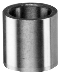
- Least expensive
- Typically for single stage drilling operations
- Permits close spacing
- Mounts flush with top of jig plate
- Length is measured overall
Press Fit Bushing Installation
First, lubricate the inside diameter of the mounting hole and the outside diameter of the bushing/liner.
Second, use an arbor press to press the bushing/liner into place. If an arbor press is not available, draw the bushing/liner into place by tightening two steel plates connected by a nut and bolt. Maintain centerline perpendicularity.
Bushing Features
- All bushings that are ground on the O.D. are held within .012 mm concentricity T.I.R. (Total Indicator Reading).
- Longer lengths than standard or excessively counterbored bushings will meet the above tolerances at the drill exit end only.
- All Acme bushings are manufactured with a blended radius at the drill entrance end unless specified otherwise.
- All Press Fit bushings have a chamfer and ground lead on the exit end.
- Standard and Special bushings will be manufactured from thru-hardened tool steel and heat treated to 61-65 Rockwell “C” unless instructed otherwise by the customer.
- No-Counterbore bushings will be supplied unless requested otherwise. No-Counterbore bushings allow for truer alignment, more accurate holes, less tool wear, and less problems with chips packing up in the I.D. of the bushing.
| Nominal O.D. | Recommended Hole Size | ||
|---|---|---|---|
| 4 | to | 6 | Nominal +0/+.012 |
| 7 | to | 10 | Nominal +0/+.015 |
| 12 | to | 18 | Nominal +0/+.018 |
| 22 | to | 30 | Nominal +0/+.021 |
| 35 | to | 48 | Nominal +0/+.025 |
| 55 | to | 78 | Nominal +0/+.030 |
| 85 | to | 115 | Nominal +0/+.035 |
| 125 | Nominal +0/+.040 | ||
Head Press Fit Bushings – Type HM
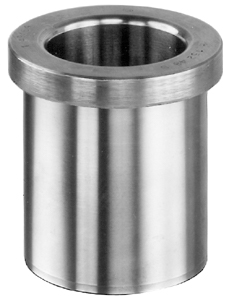
- Same as Plain Press Fit but with head (or shoulder) on the drill entry end
- Head prevents heavy axial loads from forcing bushing through jig hole
- Flush mount by counterboring jig plate to fit bushing head
- Length is measured overall
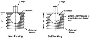
Slip-Fixed Renewable Bushings – Type SFM
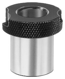
- Fixed and removable options on one knurled head for easier use
- Used with liner, permanently pressed into jig
- Held in place by lockscrew or clamp which fits a milled recess in the head
- Fixed mode for runs longer than life of bushing
- Slip mode for multiple operations on the same holes (such as drilling followed by reaming)
- O.D. has a slip fit tolerance for easy insertion or removal from the liner
- Length is measured under the head
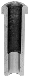
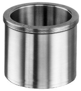
Plain Liners – Type PM
- Used with Slip-Fixed Renewable bushings to provide precise location point
- Permits interchange of Type SFM bushings with varied I.D.’s – without affecting centerline accuracy
- Permanently pressed into jig plate – for life of the jig
- Protects jig plate hole from wear caused by frequent bushing replacement
- Used where little impact or force will occur on the SF bushing’s head
- Plain Liners are the same as Plain Press Fit Bushings
Head Liners – Type HM
- Similar to Plain Liners but with a head or shoulder
- Use with Slip-Fixed Renewable bushings whenever excessive pounding or force will occur during operation
- Head prevents liner from being pushed through jig plate
- Flush mount by counterboring top of hole in jig plate
- Length is measured overall
- Head Liners are the same as Head Press Fit Bushings
Bushing Installation
Production accuracy requires extra care when preparing mounting holes and installing bushings/liners. The following factors should be considered: interference fits, alignment, chip clearance, and how close the bushing is to the workpiece.
Because of the many variables, no definite rules can substitute for the skill and judgment of the experienced toolmaker.
Interference Fits
Interference holds press fit bushings in the jig plate. Too much interference may cause a number of problems:
- jig plate distortion;
- bellmouthing (bushing/liner walls bow inward);
- tool seizure, or
- trouble with slip-fixed renewable fitting into the liner. Too little interference may allow slippage, thus causing inaccurately drilled holes.
Mounting Hole Preparation
It is recommended that all mounting holes be jig bored or sized with a reamer to assure roundness. Bushings tend to assume the shape of the hole they are pressed into. See chart below for recommended size.
The recommended installation hole size should be in accordance with metric tolerance class H7.
| Nominal O.D. | Recommended Hole Size |
|---|---|
| 4 to 6 | Nominal +0/+.012 |
| 7 to 10 | Nominal +0/+.015 |
| 12 to 18 | Nominal +0/+.018 |
| 22 to 30 | Nominal +0/+.021 |
| 35 to 48 | Nominal +0/+.025 |
| 55 to 78 | Nominal +0/+.030 |
| 85 to 115 | Nominal +0/+.035 |
| 125 | Nominal +0/+.040 |
Press Fit Bushing Installation
First, lubricate the inside diameter of the mounting hole and the outside diameter of the bushing/liner.
Second, use an arbor press to press the bushing/liner into place. If an arbor press is not available, draw the bushing/liner into place by tightening two steel plates connected by a nut and bolt. Maintain centerline perpendicularity.
Bushing Features
• All bushings that are ground on the O.D. are held within .012 mm concentricity T.I.R. (Total Indicator Reading).
• Longer lengths than standard or excessively counterbored bushings will meet the above tolerances at the drill exit end only.
• All Acme bushings are manufactured with a blended radius at the drill entrance end unless specified otherwise.
• All Press Fit bushings have a chamfer and ground lead on the exit end.
• Standard and Special bushings will be manufactured from thru-hardened tool steel and heat treated to 61-65 Rockwell “C” unless instructed otherwise by the customer.
• No-Counterbore bushings will be supplied unless requested otherwise. No-Counterbore bushings allow for truer alignment, more accurate holes, less tool wear, and less problems with chips packing up in the I.D. of the bushing.
Inside Diameter Tolerances
The minimum and maximum allowance for the Inside Diameter of standard bushings is in accordance with metric tolerance class G6. Special bushings will be supplied with the tolerances shown, unless specified otherwise.
Standard Drill Bushings:
| I.D. Range (Drill Size) | Standard I.D. Tolerance (add to nominal I.D.) |
|---|---|
| 0.35 to 3.00 | +.002 to +.008 |
| 3.01 to 6.00 | +.004 to +.012 |
| 6.01 to 10.00 | +.005 to +.014 |
| 10.01 to 18.00 | +.006 to +.017 |
| 18.01 to 30.00 | +.007 to +.020 |
| 30.01 to 50.00 | +.009 to +.025 |
| 50.01 to 80.00 | +.010 to +.029 |
| 80.01 to 105.00 | +.012 to +.034 |
| I.D. Range (Reamer Size) | I.D. Tolerance (add to nominal I.D.) |
|---|---|
| 1.00 to 3.00 | +.006 to +.012 |
| 3.01 to 6.00 | +.010 to +.018 |
| 6.01 to 10.00 | +.013 to +.022 |
| 10.01 to 18.00 | +.016 to +.027 |
| 18.01 to 30.00 | +.020 to +.033 |
Reamer Bushings are considered specials and are priced accordingly. When ordering specify the letters “RM” after the I.D.
Outside Diameter Tolerances
The minimum and maximum metric tolerance for the Outside Diameter of standard press fit bushings is class s6 and class h5 for slip-fixed renewable bushings.
Ordering Information
To order metric bushings please provide the quantity required, ANSI Symbol, and inside diameter. The order for 26 pieces of a 38 mm I.D., by 55 mm O.D., by 30 mm long, Type PM bushing should appear as follows:
| Quantity | Type | O.D. | Lgth | I.D. |
|---|---|---|---|---|
| 26 pieces | PM | – 55 | – 30 | – 38.00 |